speedmaster20d wrote:
I did some digging in the facts, that means Sony's publications in peer reviewed journal, not internet rumors.
It turns out that Sony actually published the A1 sensor design and featured at ISSCC 2021 titled
ISSCC 2021: Sony 50.1MP Full-Frame Sensor with Sigma-Delta ADC and kTC Noise Reduction
Sony's technical paper reveals the facts and repeals fiction, rumors and speculations.
I attached the PDF down below,
what the paper reveals are several feature for the A1 sensor (to ones skilled in the art)
* column-parallel ΔΣ ADC
* pipelined S&H + kTC cancellation
* simultaneous multi-row pipeline stages with heavy parallel processing to achieve high FPS
However one not skilled in the art would easily confuse these two fundamental concepts as Dave Clark also pointed out earlier in this thread.
(1) charge transfer / pixel read (physical rolling shutter mechanism)
vs
(2) downstream conversion / ADC / processing pipeline
That distinction is crucial. The rolling shutter is result of (1) not (2)
what the paper reveals in horizontal scan diagram is consistent with row-by-row (or line-by-line) charge transfer with heavy downstream pipelining that was novel.
The converted photons are locked into electrical charge, and the charge transfer is row by row. but in parallel we have digital operation that can happen like below.
So while row N is being converted:
* row N+1 is being sampled
* row N−1 is in ADC stage
* row N−2 is in digital readout
the row N does not have to wait for row N-1 digital stages to finish, it just rolls on....
So as far as Sony A1 is concerned facts align and sensor architecture is consistent with the simple fan test, because of course there are no "alternative facts".
There is no evidence whatsoever to hint at multiple physically separated rows transferring charge simultaneously as a unit for A1 . That would require:
* multi-row global transfer gates
* or charge-domain batching memory per row group
and would be very unique. There is ZERO evidence of this and from a technical point of view it makes no sense (again to the skilled in the art).
and to understand what is really happening in cameras that show a certain different signature we need this kind of technical document to look at and should refrain from presenting speculations as facts.
good observations and data are facts, but hypothesis are not facts until proven beyond a reasonable doubt ...Show more →
That is an amazing find, thanks for sharing it, and thanks for applying your skill in the art in explaining it. I was 100% wrong on this and am deeply humbled. Apologies for my erroneous speculations.
speedmaster20d wrote:
the slope does not change in APS-C mode, it's the same. Slope is limited by sensor electronics not FoV or anything like that.
if you want to get same FoV in APS-C as FF you have to walk quite a bit back from the bird that will reduce the rotational speed as you pan from much farther away and makes the distortion less .... but no one would switch to APS-C and the walk back from the bird to end up with a low resolution image of a far bird.... doesn't makes sense really
It depends on what's being compared. People use crop mode because they can't fill the frame. If one is comparing 400mm at crop with 400mm at full frame, then yes, the slope is the same. If one is comparing 400mm at crop with 600mm at full frame because they don't want to afford 600mm, I think the slope is better on 400mm at crop.
snapsy wrote:
That is an amazing find, thanks for sharing it, and thanks for applying your skill in the art in explaining it. I was 100% wrong on this and am deeply humbled. Apologies for my erroneous speculations.
thank you for the discussions, I enjoyed it and we all got something useful out of it
tctmp wrote:
It depends on what's being compared. People use crop mode because they can't fill the frame. If one is comparing 400mm at crop with 400mm at full frame, then yes, the slope is the same. If one is comparing 400mm at crop with 600mm at full frame because they don't want to afford 600mm, I think the slope is better on 400mm at crop.
This is how I think about this problem
1. The sensor scan slope is the same value regardless of the APS-C crop or FF (at least for stills that I tested, I cannot test it for video) it does not change whether a 100mm lens is mounted or 800mm lens is mounted or whether you are closer or farther away (it's a fixed physical quantity)
2. the distortion is a function of : 2.a. the scan slope (fixed) 2.b. the horizontal movement of a fixed reference on the sensor plane during the read out time as result of photographer panning , let's call it dx
3. dx = V x readout time, where V is velocity of a fixed reference on the sensor plane when panning.
4. V can be calculated from 4.a panning speed (angular velocity) which is in sync with BIF 4.b the distance of the bird to the photographer 4.c the focal length of the lens ( 4.c is a weak factor) using laws of optics and geometry
the user cannot change the readout time, nor can they change the bird's flight speed (they have to pan as fast as the bird if they want to capture the bird), But user can change 4.b by getting closer or farther from the subject, or 4.c by using a different lens
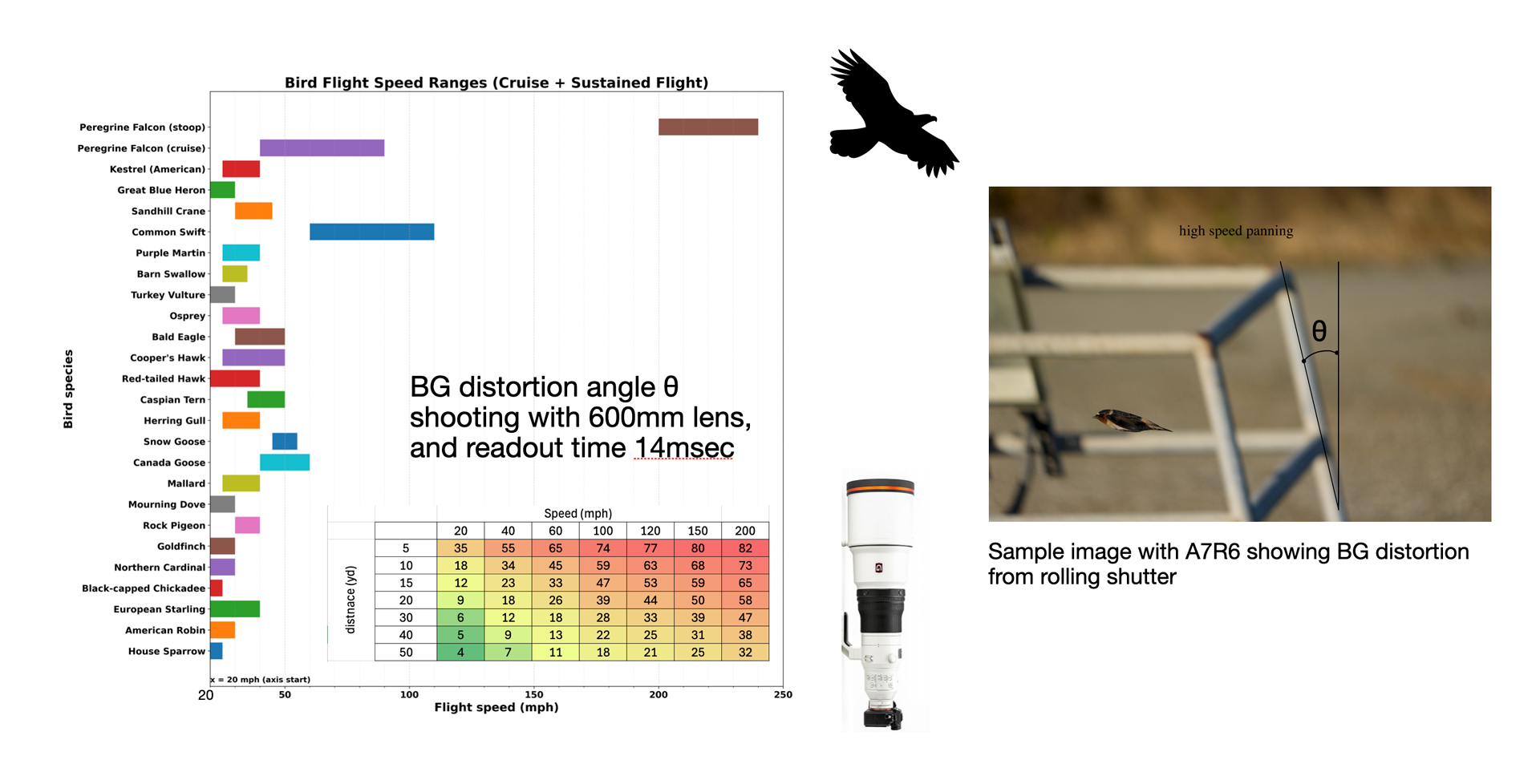
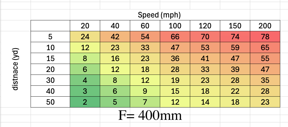
I won't bore you with the math, but the result of the calculation is shown in the table attached. I defined, somewhat arbitrarily, distortion as the slant angle of perfectly vertical feature like the image below. I have subjectively found that an angle of 10 degree or higher is quite obvious and thus color coded the table.
you can map your scenario to this table to see whether it improves or degrades the distortion
e.g. you use crop mode, it makes no difference as the crop is not a variable in the math
but say you use the crop made then walk back from the subject using the same lens the distortion becomes less because the velocity of the background on sensor plane decreases ....
hope this helps
I generated this table for 600mm lens in the first attachment and the 2nd attachment shows the same table but for a 400mm lens. the difference is no that large as in both cases the subject distance is >> focal length which is always the case for bird photography
I used AI to find estimates for each species flight speed. it may not be 100% accurate
speedmaster20d wrote:
This is how I think about this problem
1. The sensor scan slope is the same value regardless of the APS-C crop or FF (at least for stills that I tested, I cannot test it for video) it does not change whether a 100mm lens is mounted or 800mm lens is mounted or whether you are closer or farther away (it's a fixed physical quantity)
2. the distortion is a function of : 2.a. the scan slope (fixed) 2.b. the horizontal movement of a fixed reference on the sensor plane during the read out time as result of photographer panning , let's call it dx
3. dx = V x readout time, where V is velocity of a fixed reference on the sensor plane when panning.
4. V can be calculated from 4.a panning speed (angular velocity) which is in sync with BIF 4.b the distance of the bird to the photographer 4.c the focal length of the lens ( 4.c is a weak factor) using laws of optics and geometry
the user cannot change the readout time, nor can they change the bird's flight speed (they have to pan as fast as the bird if they want to capture the bird), But user can change 4.b by getting closer or farther from the subject, or 4.c by using a different lens
I won't bore you with the math, but the result of the calculation is shown in the table attached. I defined, somewhat arbitrarily, distortion as the slant angle of perfectly vertical feature like the image below. I have subjectively found that an angle of 10 degree or higher is quite obvious and thus color coded the table.
you can map your scenario to this table to see whether it improves or degrades the distortion
e.g. you use crop mode, it makes no difference as the crop is not a variable in the math
but say you use the crop made then walk back from the subject using the same lens the distortion becomes less because the velocity of the background on sensor plane decreases ....
hope this helps
I generated this table for 600mm lens in the first attachment and the 2nd attachment shows the same table but for a 400mm lens. the difference is no that large as in both cases the subject distance is >> focal length which is always the case for bird photography
I used AI to find estimates for each species flight speed. it may not be 100% accurate ...Show more →
Thanks for the inputs. I agree len's angular movement and the horizontal distance traveled stay the same regardless of the focal length. However, in my thinking, the vertical length in the frame is a function of the len's focal length. And slope is a function of both horizontal movement and vertical length. Let me throw up some numbers for illustration.
Let's say there is a very tall vertical pole that from the 400mm full frame you see a segment of 6 meters tall. Let's say during the full frame scan time, the bird travels 3 meters horizontally, so you would have panned 3 meters. So the slope observed on the pole is 3/6. In the crop frame using the same lens, you will only see a segment of 4 meters tall, and during the crop scan time, the bird travels 2 meters, you would have panned 2 meters horizontally. So slope is 2/4, which is still the same. That part I think we all agree.
Now if we put on a 600mm lens on full frame. You will only see a segment of 4 meters tall of the pole in the picture. However to follow the bird, you would still have panned 3 meters horizontally during the full frame scan time. So the slope now becomes 3/4 which is worse compared to 1/2.
Let me know if you see something I missed in my reasoning. I think it's still consistent with your walking back scenario. However, I don't think people contemplating using crop frame is planning to walk back, rather they want to stay in the same spot while trying to get the framing/composition which they otherwise need a longer lens to fill the full frame. So it seems reasonable to compare shooting a shorter lens on crop with shooting a longer lens on full frame, at identical conditions.
tctmp wrote:
Thanks for the inputs. I agree len's angular movement and the horizontal distance traveled stay the same regardless of the focal length. However, in my thinking, the vertical length in the frame is a function of the len's focal length. And slope is a function of both horizontal movement and vertical length. Let me throw up some numbers for illustration.
Let's say there is a very tall vertical pole that from the 400mm full frame you see a segment of 6 meters tall. Let's say during the full frame scan time, the bird travels 3 meters horizontally, so you would have panned 3 meters. So the slope observed on the pole is 3/6. In the crop frame using the same lens, you will only see a segment of 4 meters tall, and during the crop scan time, the bird travels 2 meters, you would have panned 2 meters horizontally. So slope is 2/4, which is still the same. That part I think we all agree.
Now if we put on a 600mm lens on full frame. You will only see a segment of 4 meters tall of the pole in the picture. However to follow the bird, you would still have panned 3 meters horizontally during the full frame scan time. So the slope now becomes 3/4 which is worse compared to 1/2.
Let me know if you see something I missed in my reasoning. I think it's still consistent with your walking back scenario. However, I don't think people contemplating using crop frame is planning to walk back, rather they want to stay in the same spot while trying to get the framing/composition which they otherwise need a longer lens to fill the full frame. So it seems reasonable to compare shooting a shorter lens on crop with shooting a longer lens on full frame, at identical conditions....Show more →
I think we have some terminology gap here
the slope I refer to is the scan scope i.e the rate at which the sensor scans the row (please see the PDF paper to understand). we call all that sensor_readout_slope
it seems you are referring to something else as slope here. With that in mind we can walk through the correct math
let's correct these 2 assumptions that you used above
1. Geometry: panning is measured in radiant (angle) not meters . if the bird is traveling at speed V at distance d the panning speed or w = V / d [radiant / sec ] it does not depend on your lens or crop vs no crop. for example if a plane is traveling at 500 mph but it is 5 miles aways you barely need to pan when tracking it.
2. Laws of optics : what you call slope cannot be calculated on the subject plane, but has to be calculated on the image sensor plane which is what we care about for rolling shutter and is exactly what I did. it can easily be proven that it is not dependent on the crop factor per below
let say the hight of the sensor is h (e.g. 24mm for FF and < 24mm in crop mode)
The horizontal shift on the sensor plane, dx is computed using lens maker's formula : dx = tan(w x t) x d x F / (d-F) (1) I will simplify this as it become messy to type in text but the table I provided uses the full formula
for BIF d>>F and w x t is a small number so dx ~ w x t F = V x F x t /d (2)
F = focal length (m)
d = distance to bird (m)
w = panning speed [radiant /sec ]
t = readout time (sec) = h x sensor_readout_slope
V = BIF flight speed (m/sec)
the distortion angle theta can be computed simply tan(theta) = dx / h = V x F x t / d x 1/h (3)
but we know t = h X sensor_readout_slope we substitute in (3)
than(theta) = V x F x sensor_readout_slope / d (4)
h cancels out and has no effect --> APS Crop has no effect at all
speedmaster20d wrote:
I think we have some terminology gap here
the slope I refer to is the scan scope i.e the rate at which the sensor scans the row (please see the PDF paper to understand). we call all that sensor_readout_slope
it seems you are referring to something else as slope here. With that in mind I think you have several flaws in your logic.
1. Incorrect geometry framework : using "meters or length" for panning, panning is measured in radiant (angle) not meter. if the bird is traveling at speed V at distance d the panning speed or w = V / d [radiant / sec ] it does not depend on your lens or crop vs no crop. for example if a plane is traveling at 500 mph but it is 5 miles aways you barely need to pan when tracking it.
2. incorrect methodology (ignoring Laws of optics) : what you call slope cannot be calculated on the subject plane, but has to be calculated on the image sensor plane which is what we care about for rolling shutter and is exactly what I did. it can easily be proven that it is not dependent on the crop factor per below
let say the hight of the sensor is h (e.g. 24mm for FF and < 24mm in crop mode)
The horizontal shift on the sensor plane, dx is computed using lens maker's formula : dx = tan(w x t) x d x F / (d-F) (1) I will simplify this as it become messy to type in text but the table I provided uses the full formula
for BIF d>>F and w x t is a small number so dx ~ w x t F = V x F x t /d (2)
F = focal length (m)
d = distance to bird (m)
w = panning speed [radiant /sec ]
t = readout time (sec) = h x sensor_readout_slope
V = BIF flight speed (m/sec)
the distortion angle theta can be computed simply tan(theta) = dx / h = V x F x t / d x 1/h (3)
but we know t = h X sensor_readout_slope we substitute in (3)
than(theta) = V x F x sensor_readout_slope / d (4)
h cancels out and has no effect --> APS Crop has no effect at all
so while you description is bit intuitive it is mathematically incorrect which leads to only partially correct predictions ...Show more →
Good discussion. Yes, I'm using the "slope" loosely. I mean in this case, tan(theta), so bigger slope, bigger theta.
Can you clarify what d means in your definition? Does it mean from your location to the bird/pole? If so, that's on an orthogonal plane to the plane where your theta is drawn. Theta is on the image/sensor plane, and it has nothing to do with the distance from camera to the bird. If d means something else, let me know. Thanks.
Edit: I just saw you made some edit. Yes, cropping on a same lens does not change the slope/theta. But even with matching framing, shorter lens on crop has less slope/theta compared to longer lens on full frame.
tctmp wrote:
Good discussion. Yes, I'm using the "slope" loosely. I mean in this case, tan(theta), so bigger slope, bigger theta.
Can you clarify what d means in your definition? Does it mean from your location to the bird/pole? If so, that's on an orthogonal plane to the plane where your theta is drawn. Theta is on the image/sensor plane, and it has nothing to do with the distance from camera to the bird. If d means something else, let me know. Thanks.
d is the distance of the sensor plane to the subject (BIF)
the angular velocity is proportional to 1/d and theta is connected to d though the imaging condition of the lens -you cannot ignore the optics, the light path from subject to the sensor is not straight, it is bent (refracted) by the lens
tctmp wrote:
Good discussion. Yes, I'm using the "slope" loosely. I mean in this case, tan(theta), so bigger slope, bigger theta.
Can you clarify what d means in your definition? Does it mean from your location to the bird/pole? If so, that's on an orthogonal plane to the plane where your theta is drawn. Theta is on the image/sensor plane, and it has nothing to do with the distance from camera to the bird. If d means something else, let me know. Thanks.
Edit: I just saw you made some edit. Yes, cropping on a same lens does not change the slope/theta. Shorter lens on crop has less slope/theta compared to longer lens on full frame. I think we all agree now. ...Show more →
yes it seems we have same conclusion
I would rephrase it like this to make it more accurate (or I should say less confusing)
shorter lens makes it better (lower theta) whether you use crop or not
your argument : why not use a shorter lens and crop it ? it is better for distortion (true statement)
my (subjective and personal answer) : I try not to crop, I prefer to use long focal length and use all the 60 mega pixel I paid for
but my answer here is no longer fact for everyone... just mine
speedmaster20d wrote:
d is the distance of the sensor plane to the subject (BIF)
the angular velocity is proportional to 1/d and theta is connected to d though the imaging condition of the lens -you cannot ignore the optics, the light path from subject to the sensor is not straight, it is bent (refracted) by the lens
In this case, your formula for theta is incorrect. Your formula just gives back the panning angle from the camera, that is how much your lens rotates during the scanning. It's not the angle on the image plane regarding how much a vertical line tilts.
But anyway, we agree on the conclusion, same lens, no effect on slope/theta on the crop. For same framing, shorter lens on crop has less slope than longer lens on full frame. That's good enough.
tctmp wrote:
In this case, your formula for theta is incorrect. Your formula just gives back the panning angle from the camera, that is how much your lens rotates during the scanning. It's not the angle on the image plane regarding how much a vertical line tilts.
you did not pay close enough attentions to the math I am afraid, despite my effort, the image sensor is attached to the camera and it rotates with the same rate as you rotate the camera. dx is computed on the image plane , the key is dx here.
It seems to me you are not very comfortable with the math presented here , I don't have a better way to explain it. One suggestion is to pose the problem to AI have it walk you through and derive the same thing, maybe it helps, basic geometrical optics text books would help too
I still do not understand what you mean by simialr framing, but I would refer to the math again.
speedmaster20d wrote:
you did not pay attentions to the math I am afraid despite my effort, the image sensor is attached to the camera and it rotates with the same rate as you rotate the camera. dx is computed on the image plane
I seems to me you are not very comfortable with the math, I don't have a better way to explain it. One suggestion is to pose the problem to AI have it walk you through and derive the same thing, maybe it helps.
Please don't get there, I understand this math thing quite decently, and I already mentioned the issue I saw in your formula. My original and only position, you now agree. Let's just leave at that.
tctmp wrote:
Please don't get there, I understand this math thing quite decently, and I already mentioned the issue I saw in your formula. Let's just leave at that.
I seriously suggest you pose this question to AI and see what it gives.
good luck!
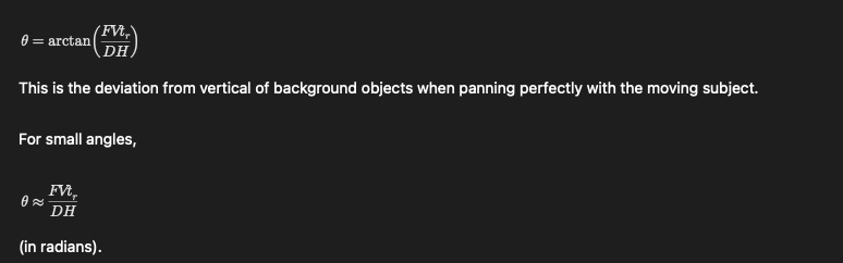
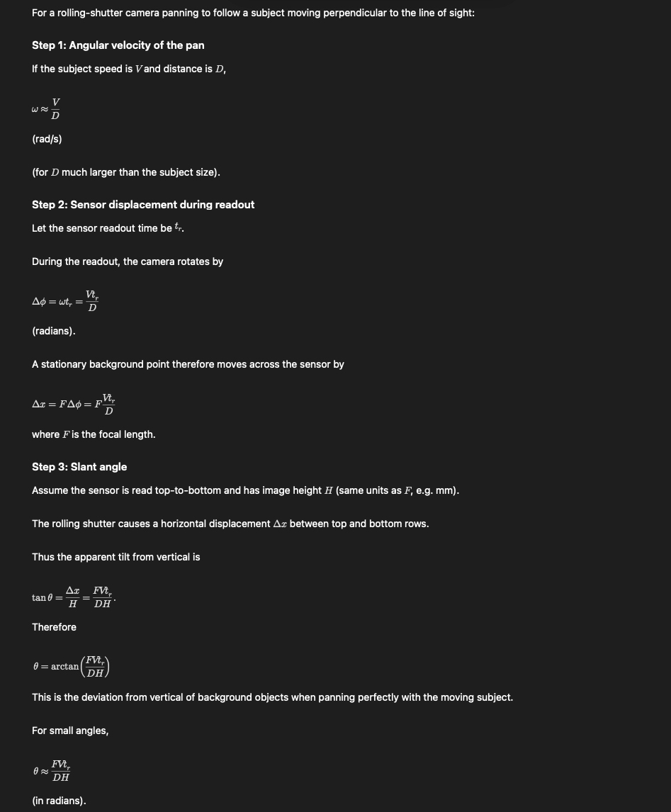
Edit: out of curiosity I did it myself and attach Chat GPT's answer below. looks familiar to (4) perhaps it has already made forums like this obsolete
speedmaster20d wrote:
I seriously suggest you pose this question to AI and see what it gives.
good luck!
Edit: out of curiosity I did it myself and attach Chat GPT's answer below. looks familiar to (4) perhaps it has already made forums like this obsolete
Yes, FVt is a function of focal length only (V is constant), and DH is the height of the sensor. t/DH is a constant too. So that matches what my illustration and also has nothing to do with the distance from the camera to the object.
tctmp wrote:
Yes, FVt is a function of focal length only, and DH is the height of the sensor. So that matches what my illustration and also has nothing to do with the distance from the camera to the object.
"DH is the height of sensor "
did you not read the "D" in the denominator ?? D is distance and H is height,
" has nothing to do with the distance from the camera to the object" seriously man ?
I print from chat GPT, you can argue with it, it has much more patience than myself
It is crystal clear to me that this discussion is fruitless as one side does not speak the language of the other.
duncangr wrote:
I recently used an R5m2 shooting swallows and the jagis on the wings were clearly visible and awful.
I have seen this on the A9 where they are barely visible but have never seen this on any A1/A1ii or A9iii images - and I have many thousands from the A1 - the edges all appear to be consistently smooth like the edges in the fan images above.
Couldn't find any evidence of these artifacts in the Z9 swallow images either.
Z9 sensor is a variant of the A1 sensor so no surprise there. I assume that R5II image is at high magnification and I can barely see the "horrible" jaggies and I doubt anyone would notice them at 100%. They look less than the A9 jaggies. I never ever noticed jaggies at all on my A9 in 40000 shots, but I never looked beyond 100%.
did you not read the "D" in the denominator ?? D is distance and H is height, seriously man ?
I print from chat GPT, you can argue with it, it has much more patience than myself
It is crystal clear to me that this discussion is fruitless as one side does not speak the language of the other.
peace now
Ok, now you posted the full chat, here is the reading. D is a constant since we are staying at the same location. t/H is constant. So theta is just a function of F. That has always been my point.
Your original argument was F, t and D somehow cancel out. I decided to compare your formula with GPT's, and here is your mistake. You said H cancels out, but you left t there in your formula. That's incorrect, it's t/H that's constant. So you made mistake in your simplification.
In fact, if one plugs in any number into the GPT formula, between two cases of F=600 and 400, with same D, t/H, V, the ratio of two tan(theta) which I defined as slopes matches exactly my numerical illustration. I don't need GPT to tell me how to compute this.
I actually am a little bit disappointed that you feel the need to make the other unnecessary comments though.
Pixel Perfect wrote:
Z9 sensor is a variant of the A1 sensor so no surprise there. I assume that R5II image is at high magnification and I can barely see the "horrible" jaggies and I doubt anyone would notice them at 100%. They look less than the A9 jaggies. I never ever noticed jaggies at all on my A9 in 40000 shots, but I never looked beyond 100%.
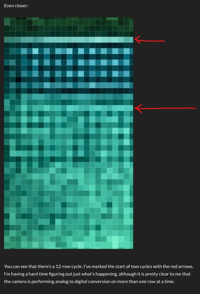
Z8/Z9 exhibits the 12-row staircase pattern, both in Jim Kasson's test and also in third-party flash photography. Which brings into question whether the Z8/Z9 share the same core sensor IP as the A1, which is something I previously assumed based on their nearly-identical readout times after normalizing for their row count differences.
speedmaster20d wrote:
I did some digging in the facts, that means Sony's publications in peer reviewed journal, not internet rumors.
It turns out that Sony actually published the A1 sensor design and featured at ISSCC 2021 titled
ISSCC 2021: Sony 50.1MP Full-Frame Sensor with Sigma-Delta ADC and kTC Noise Reduction
Sony's technical paper reveals the facts and repeals fiction, rumors and speculations.
I attached the PDF down below,
what the paper reveals are several feature for the A1 sensor (to ones skilled in the art)
* column-parallel ΔΣ ADC
* pipelined S&H + kTC cancellation
* simultaneous multi-row pipeline stages with heavy parallel processing to achieve high FPS
However one not skilled in the art would easily confuse these two fundamental concepts as Dave Clark also pointed out earlier in this thread.
(1) charge transfer / pixel read (physical rolling shutter mechanism)
vs
(2) downstream conversion / ADC / processing pipeline
That distinction is crucial. The rolling shutter is result of (1) not (2)
what the paper reveals in horizontal scan diagram is consistent with row-by-row (or line-by-line) charge transfer with heavy downstream pipelining that was novel.
The converted photons are locked into electrical charge, and the charge transfer is row by row. but in parallel we have digital operation that can happen like below.
So while row N is being converted:
* row N+1 is being sampled
* row N−1 is in ADC stage
* row N−2 is in digital readout
the row N does not have to wait for row N-1 digital stages to finish, it just rolls on....
So as far as Sony A1 is concerned facts align and sensor architecture is consistent with the simple fan test, because of course there are no "alternative facts".
There is no evidence whatsoever to hint at multiple physically separated rows transferring charge simultaneously as a unit for A1 . That would require:
* multi-row global transfer gates
* or charge-domain batching memory per row group
and would be very unique. There is ZERO evidence of this and from a technical point of view it makes no sense (again to the skilled in the art).
and to understand what is really happening in cameras that show a certain different signature we need this kind of technical document to look at and should refrain from presenting speculations as facts.
good observations and data are facts, but hypothesis are not facts until proven beyond a reasonable doubt ...Show more →
In light of the A1 disclosures, I wonder how much can be inferred about the a7rVI's readout architecture based on the differential in readout rates of14-bit vs 12-bit. For reference, here are various 14-bit vs 12-bit readout measurements:
a7rIV: 18.26 ms vs 9.97 ms: 45.50%
a7rIII: 25.37 ms vs 14.35 ms: 43.43%
a7rVI: 19.7 ms vs 14.1 ms: 28.43%
S1 II: 83.88 ms vs 69.10 ms: 17.62%
The a7rIII and a7rIV are not stacked. Both the a7rVI and S1 II are partially-stacked sensors (and without embedded DRAM on the sensor wafer complex). Unfortunately none of the fully-stacked sensors I've measured have a 12-bit mode, so I don't know their deltas.
If we assume all sensors share the same sigma delta ADCs (not sure how safe an assumption that is), then I wonder if we can infer that the partially-stacked's relatively lower improvement of 14-bit vs 12-bit as a function of the pipelining hiding some of the cost of the ADC. Thoughts?
snapsy wrote:
Z8/Z9 exhibits the 12-row staircase pattern, both in Jim Kasson's test and also in third-party flash photography. Which brings into question whether the Z8/Z9 share the same core sensor IP as the A1, which is something I previously assumed based on their nearly-identical readout times after normalizing for their row count differences.
it's too bad the blog owner is not here to comment. When I read his comments he does not claim to know what is causing this issue
"’I’m having a hard time figuring out just what’s happening, although it is pretty clear to me that the camera is performing analog to digital conversion on more than one row at a time."
as we know now the conversion can happen in parallel so this his second part of the statement can be true but neither is he saying nor can we conclude that the charge transfer itself is happening for groups of row... or that it is responsible for this artifact
I don't think we can explain this bizarre artifact very simply. In fact the patten looks as if there is something different between even and odd columns in those 12 rows... it seems as if one group of rows did not even readout or had their level shifter mess up .... but somehow it only shows up with moving light....
If we had access to the raw images, we could split each image into 2 images, one for even columns and one for off columns to see if the bands appear in just one or both images to shed more light....
It is very difficult to say what is causing this, but it this looks some kind of design bug, some kind unwanted effect that is not result of just rolling shutter.... whatever it was it seems to have been fixed ?
I am having a hard time even coming up with a theory
He also used an analog scope (no one uses those anymore) so making an optical waveform like this is all but almost impossible at home