fredmiranda.com
Login

Moderated by: Fred Miranda
Username  


FM Forums | Sony Forum | Join Upload & Sell

1       2              4       5       end
  

Sensor and lens tilt and how to DIY adjust your equipment


inksandpaper
Offline
•
Upload & Sell: Off
p.3 #1 · Sensor and lens tilt and how to DIY adjust your equipment


Fred, firstly, congratulations on your successful shimming surgery! Please forgive the unintended alliteration :-) Very nice outcome. I'm really glad it went so smoothly so you are not put off from this adjustment technique. You've now saved an otherwise crooked lens.

You were lucky in three ways.

1. Since you shimmed at the screw position which corresponded to the out-of-focus corner, it means the focus plane was bending closer in the top and bottom left image corners, which is actually the top and bottom right sensor corners are too far from the lens, or you can say the extension is longer there. If the focus plane was actually bending further, you would have shimmed at the wrong screw positions and will need to flip the orientation. I don't know if you skipped entirely the process to determine the direction of focus plane shifting, because you didn't mention it.

2. Your mount is now unsupported and bent. The bottom right screw is now unsupported by 100 microns, because you put 20 microns on the top left and 120 microns on the bottom left screws. 100 microns is a bit much to be comfortable to me, but you said it seems fine. I would worry that the bent mount would now stress the flanges of the adapter. Mounting and dismounting may result in visible uneven wear on both the lens and adapter bayonets over time. Beware of this. That's why you need to shim the screws in pairs, as you've already realised later.

3. You didn't determine the focus distance to estimate the lens extension amount, but guessed correctly in two tries (once for the top left screw) how much the shim amount should be. Really lucky :-) But I'm glad you used a more reasonable shim amount rather than 1-4mm, which would have been way off. I was going to guess 70-100 microns of tilt in the corner comparison but I didn't know how far away the building is, so the guess could have been way off.

Fred Miranda wrote:
Thanks for the info Samuel. The subject is at infinity distance where I don't think precise camera parallelism is needed. I can repeat this test multiple times and it always show the same exact results.


You've misunderstood me. I was not referring to plane parallelism of the subject plane relative to the image plane. I was saying not to shoot with the camera rotated at an angle like this (meaning roll, not yaw direction) because you can't determine the swing (so the camera must be horizontal) and tilt (so the camera must be vertical) independently and shim at the screws correctly in pairs. That's the methodical way to go about it. Certainly one can just wing it and just go by trial and error, but you really were too lucky :-)

Your subject is also not at infinity distance. How far are those buildings from you? You might be able to measure the distance using the ruler tool in Google Maps if you don't have a laser rangefinder. Let's assume it is 3 miles or 15840 feet away. Focal length is 200mm. You shimmed by 120 microns, so that's the extension difference. That means the bottom left image corner (top right sensor corner) was focussing at 1025 feet while the top right image corner (bottom left sensor corner) was focusing at 15840 feet. That's how we use the optical formula to derive the ballpark shim amounts rather than rely purely on guesswork.

Screenshot of lens extension calculations

I will try this method with another lens but this one (Minolta 200/2.8) became well centered with what I did.

Actually the lens is already well-centered, optically. This kind of shimming cannot center your lens for you. I would be more precise and say the lens focus field tilt was optimally straightened/aligned parallel to the sensor or image plane with what you did.


Sep 12, 2020 at 11:22 PM
Fred Miranda
Offline
Admin
Upload & Sell: On
p.3 #2 · Sensor and lens tilt and how to DIY adjust your equipment


inksandpaper wrote:
Fred, firstly, congratulations on your successful shimming surgery! Please forgive the unintended alliteration :-) Very nice outcome. I'm really glad it went so smoothly so you are not put off from this adjustment technique. You've now saved an otherwise crooked lens.

You were lucky in three ways.

1. Since you shimmed at the screw position which corresponded to the out-of-focus corner, it means the focus plane was bending closer in the top and bottom left image corners, which is actually the top and bottom right sensor corners are too far from the lens, or you can say the extension is longer
...Show more →

Hi Samuel,

Your mount is now unsupported and bent. The bottom right screw is now unsupported by 100 microns, because you put 20 microns on the top left and 120 microns on the bottom left screws. 100 microns is a bit much to be comfortable to me, but you said it seems fine. I would worry that the bent mount would now stress the flanges of the adapter. Mounting and dismounting may result in visible uneven wear on both the lens and adapter bayonets over time. Beware of this. That's why you need to shim the screws in pairs, as you've already realised...Show more →

I did notice a small but noticeable tightening when mounting/unmounting the lens+adapter. That's probably due to mount bend as you mentioned. I now understand how important it is to shim in pairs. Lesson learned.

I've removed the shims and started over by adding 100 microns to both screws (top and bottom left) and the result is very similar. Correction for tilt was not needed. At least now, the mount is flat.

Since you shimmed at the screw position which corresponded to the out-of-focus corner, it means the focus plane was bending closer in the top and bottom left image corners, which is actually the top and bottom right sensor corners are too far from the lens, or you can say the extension is longer there. If the focus plane was actually bending further, you would have shimmed at the wrong screw positions and will need to flip the orientation. I don't know if you skipped entirely the process to determine the direction of focus plane shifting, because you didn't mention it.

Before the shimming, when I focused at center, the top/bottom left corner were OOF. When focusing at the corner, I noticed that I was focusing closer, so it made sense to add the shims there instead of the other side.

The subject was at 3.1 miles so your calculation is correct.

Actually the lens is already well-centered, optically. This kind of shimming cannot center your lens for you. I would be more precise and say the lens focus field tilt was optimally straightened/aligned parallel to the sensor or image plane with what you did

Yes, I meant the focus plane swing was corrected. The lens was not decentered.

Thank you for your comments. I've learned a lot from this thread.


Sep 13, 2020 at 01:22 PM
Fred Miranda
Offline
Admin
Upload & Sell: On
p.3 #3 · Sensor and lens tilt and how to DIY adjust your equipment


BTW: To test my A7R IV camera mount/sensor parallelism, I've ordered these items to use with my Leica 135/4 M-mount lens (cheap and sharp wide open):

1) LM-EOS Adapter Ring for Leica M Mount Lens to Canon EOS: https://www.ebay.com/itm/283636025024

2) Kipon Shift 15mm Adapter for Canon EOS EF Lens to Sony E Mount Camera NEX 360º: https://www.ebay.com/itm/124024665751


Sep 13, 2020 at 01:45 PM
Fred Miranda
Offline
Admin
Upload & Sell: On
p.3 #4 · Sensor and lens tilt and how to DIY adjust your equipment


Oh no! I just saw this:

"Update 10 Sep 2020: I’ve just learned from Ilija that the newer Sony Alpha mirrorless cameras (a9, a7R III, a7 III, a9II, a7R IV, a7S III) using 6 screws for the bayonet mount rather than 4, have a different bayonet mount design. Part of the bayonet is held down by the front body case itself, in addition to being held by the screws. It is highly likely that this change prevents these newer cameras from being shimmed at the mount. One would have to take apart nearly the entire camera to reach the sensor and adjust it there instead."

Did you try adjusting your A7R IV Samuel?


Sep 13, 2020 at 04:22 PM
realVivek
Offline
• • • •
Upload & Sell: Off
p.3 #5 · Sensor and lens tilt and how to DIY adjust your equipment


The new bayonet design is a direct result of people asking for a more robust mount.

The sensor can be shimmed at two places:

1. Where the IBIS unit is attached to the camera chassis (this is where one finds the camera shims as well).

2. Where the sensor is attached to the IBIS unit.

Not easy.


Sep 13, 2020 at 04:27 PM
inksandpaper
Offline
•
Upload & Sell: Off
p.3 #6 · Sensor and lens tilt and how to DIY adjust your equipment


Fred Miranda wrote:
I did notice a small but noticeable tightening when mounting/unmounting the lens+adapter. That's probably due to mount bend as you mentioned. I now understand how important it is to shim in pairs. Lesson learned.


Great that you noticed the tightening, that's a very good indication that the free play in bayonet CNC machining is less than the user-introduced warpage, so it is better to re-do the adjustment just to feel reassured. Well done!

BTW is there a way to see previously edited versions of a post on the forums? I thought I've seen that function before, but now I can't find it. I recall seeing different versions of your messages on this thread at least. The paper roll question is now gone, except where I've included it in a quote in my reply. Also, I seem to recall you mentioned not needing the paper rolls but only tweezers (something to do with not having coffee ) and that it was a smooth 5-min job. Isn't it fun to take off the bayonets of these old lenses? No electronics in the way. Bayonet on and off, super quick to make any readjustments. Canon EF lenses are no fun at all. I guess you now see how it's an iterative process, especially at the start there's a bit of a learning curve. I tore my hair out a lot over the months we spent trying to figure this out. I suppose I could have peppered the article with more tips about the shimming work, but oftentimes I can't imagine what obstacles one might encounter so any advice is better crafted as the questions arise. It depends.

I've removed the shims and started over by adding 100 microns to both screws (top and bottom left) and the result is very similar. Correction for tilt was not needed. At least now, the mount is flat.

Oh, so no more tilt correction. Hmmm. Here's another tip that should be useful. You like to rotate the camera in the roll direction, not yaw, so your subject is captured at a slanted angle as you've always done in your lens tests because you want to put the subject right into the far corners (that's fine for that purpose), though I see you are not keeping the rotation consistent like in the illustration you provided (it's not important in your lens comparison tests but it is when you are working out focus swing and tilt). For example, the roll rotation in the unshimmed pair of crops for the #2 bottom left image corner is 38.5 degrees, as measured using the ruler tool in Photoshop off the guard railing of the building. It's 33 degrees (remarkably close to optimal) for the opposite #4 or top right corner. Your illustrations actually call for a consistent 33.6 degree roll rotation. And you need to compute what that skew would be with the rotation undone, with the camera upright (viewfinder pointing straight up), to be able to say 'the lens is swung'. And at right angles to that for 'tilt'. Otherwise what you are seeing is not swing, but rather some combination of swing and tilt, which makes it harder to decide how much to shim and where.

Here's a pro tip. I've very often noticed that the apparent depth of field in the corners, especially of lenses which have more optical aberrations, is seemingly greater than in the center and mid-field (mid-field can sometimes be strangely thin). And the S and T field curvatures often diverge, to add to the trouble. When you have organic detail or structural detail at a rotated angle, a wide range of field tilts combined with the depth of field can mean anything, in your case, from 80-120 microns of adjustment can still look quite balanced. You don't actually need to see into the corners for this kind of adjustment, it's not useful and blindsides one actually. I only ever look at the center portion of the image top, bottom, left and right edges. The camera is always viewfinder pointed straight up, or rotated 90 degrees anti-clockwise to the left to shoot the test scene. The test scene must have continuous detail near to far for this to work. Here's the tip: don't look only at where it's sharply in-focus, look at the near edge and far edge of the depth of field. Observe the gradient of in-focus to out-of-focus, use the blur gradient to pinpoint the true plane of focus. It is much easier this way. You might find then that you're at least 10 microns off from an optimal adjustment, because the depth of focus (not field) at f/2.8 (for any focal length) is about 23 microns, and optical aberrations in the corners increase that to perhaps ~30-40 micron's worth where it all stills looks OK.

An optimal alignment might not so important for a 200mm lens with no field curvature, but if you're looking to adjust one which has field curvature, it's much better to ensure the tilt alignment is as good as you can get it. Because then you can use compromise focus (e.g. focusing on the mid-field zone) reliably. Or you can actually focus right on the image edge and know that the other side will be perfectly balanced in focus too (even flat field lenses can benefit then). And don't worry about not looking at the corners initially, you would find they will follow and be in balance too, assuming the lens is reasonably optically centered.

Before the shimming, when I focused at center, the top/bottom left corner were OOF. When focusing at the corner, I noticed that I was focusing closer, so it made sense to add the shims there instead of the other side.

Did you mean you had to turn the lens focus ring to focus further (past the lens barrel infinity focus marker) for the left corners?

The subject was at 3.1 miles so your calculation is correct.

Wow! Lucky guess haha!

Thank you for your comments. I've learned a lot from this thread.

You're most welcome! I'm very thankful that you've so enthusiastically investigated it for yourself


Sep 13, 2020 at 05:16 PM
inksandpaper
Offline
•
Upload & Sell: Off
p.3 #7 · Sensor and lens tilt and how to DIY adjust your equipment


Fred Miranda wrote:
Oh no! I just saw this:

"Update 10 Sep 2020: I’ve just learned from Ilija that the newer Sony Alpha mirrorless cameras (a9, a7R III, a7 III, a9II, a7R IV, a7S III) using 6 screws for the bayonet mount rather than 4, have a different bayonet mount design. Part of the bayonet is held down by the front body case itself, in addition to being held by the screws. It is highly likely that this change prevents these newer cameras from being shimmed at the mount. One would have to take apart nearly the entire camera to reach the sensor
...Show more →

Edit: Fred Miranda has tried and the bayonet can be removed normally just like the older 4-screw mounts. Please ignore the below.

I didn't take apart my a7R IV when I had it, so I didn't realise until recently that the mount is not easily removable like in the older generation Sonys. Very annoying! I've mentioned it a while back on this thread. This was what I said:

I've also just learned that all the new Sony cameras with 6-screw bayonets from the a7R III onwards have different shaped front mounts which are not easily removed, and the design most likely prevents shimming because of the way the front panel clamps down on the mount. So those would require full disassembly to reach the sensor and shim there...

I wonder also about the need to adjust the camera, given the bayonet machining issue and that camera tilts are generally small. Maybe the best bet is to select a camera that is quite straight, never adjust the camera and simply shim all of one's lenses to that camera. When you switch cameras, re-shim any lenses that mate differently with the new one. And you don't need to re-shim every lens if you are mostly doing stopped-down landscape photography. Only the special primes for special work, for example. This was actually my plan when I got an a7R IV for a trip that never happened due to the pandemic, before I knew the mount was non-removable.


BTW: To test my A7R IV camera mount/sensor parallelism, I've ordered these items to use with my Leica 135/4 M-mount lens (cheap and sharp wide open):

I still think this is a worthwhile investigation since you are taking to adjusting your lenses now. You don't want any surprises later...

When you do this, you will be able to precisely know how much error is introduced by the camera, the bayonet machining differences between the camera body and lens mount and the lens focus plane skew.

Update: I've measured my Minolta to E-mount adapter for parallelism using a micrometer and all sides are equal

This is quite remarkable, by the way. I assume your micrometer's resolution is 1-micron? or 0.05 mils? All the adapters I've ever measured (not that it was that many) are not uniform in thickness to 1 micron. Even my highly overpriced and superbly well-made Novoflex EOS to E-mount adapter has an 18-micron difference at the highest and lowest points. If you imagine the bayonet face as the face of a clock, don't just measure at the 12, 3, 6 and 9 o'clock positions. I measure at least at every hourly position or in even finer steps, especially between, next to and on the mount screw positions, which can deform the mount plate sometimes.

I can't post pictures here directly, so here is a link to an illustration of that.

Edited on Sep 13, 2020 at 08:59 PM · View previous versions


Sep 13, 2020 at 05:31 PM
Fred Miranda
Offline
Admin
Upload & Sell: On
p.3 #8 · Sensor and lens tilt and how to DIY adjust your equipment


inksandpaper wrote:
BTW is there a way to see previously edited versions of a post on the forums? I thought I've seen that function before, but now I can't find it. I recall seeing different versions of your messages on this thread at least. The paper roll question is now gone, except where I've included it in a quote in my reply. Also, I seem to recall you mentioned not needing the paper rolls but only tweezers (something to do with not having coffee ) and that it was a smooth 5-min job. Isn't it fun to take off the bayonets of
...Show more →

I removed that question from my post because I found the modeling sticks (Thanks @realVivek for the idea) and didn't need the paper rolls anymore. I also removed that it was done in 5 minutes because it needed more tweaks which took more time. I don't want to give members a false impression that it's an easy job.
On the Minolta 200/2.8 HS APO, the electronics were not in the way, except that I had to be very careful not to disconnect the wires. They are very thin and soldered to the mount. Also, there is a thin coil that engages the aperture mechanism and that was worrisome as well but not too difficult to maneuver around.

This is quite remarkable, by the way. I assume your micrometer's resolution is 1-micron? or 0.05 mils? All the adapters I've ever measured (not that it was that many) are not uniform in thickness to 1 micron. Even my highly overpriced and superbly well-made Novoflex EOS to E-mount adapter has an 18-micron difference at the highest and lowest points. If you imagine the bayonet face as the face of a clock, don't just measure at the 12, 3, 6 and 9 o'clock positions. I measure at least at every hourly position or in even finer steps, especially between, next to and...Show more →

I have two. One is 0-1"/0.00005" and the other is 1-2"/0.00005"


Sep 13, 2020 at 05:53 PM
inksandpaper
Offline
•
Upload & Sell: Off
p.3 #9 · Sensor and lens tilt and how to DIY adjust your equipment


Fred Miranda wrote:
I removed that question from my post because I found the modeling sticks (Thanks @realVivek@ for the modeling sticks idea) and didn't need the paper rolls anymore. I also removed that it was done in 5 minutes because it needed more tweaks which took more time. I don't want to give members a false impression that it's an easy job.
On the Minolta 200/2.8 HS APO, the electronics were not in the way, except that I had to be very careful not to disconnect the wires. They are very thin and soldered to the mount. Also, there is a thin
...Show more →

Indeed I'm glad you made the edits, for the same reasons as you mentioned.

That's interesting, so you are not able to lift the Minolta 200/2.8's bayonet mount clear off the lens because little wires are soldered to it?


Sep 13, 2020 at 05:57 PM
Fred Miranda
Offline
Admin
Upload & Sell: On
p.3 #10 · Sensor and lens tilt and how to DIY adjust your equipment


inksandpaper wrote:
Indeed I'm glad you made the edits, for the same reasons as you mentioned.

That's interesting, so you are not able to lift the Minolta 200/2.8's bayonet mount clear off the lens because little wires are soldered to it?


I was able to lift the bayonet but not remove it. The wires are thin and the soldering very fragile. This has to be handled with care. It should be much easier with modern lenses and flex flat cables. I also use a tweezer to maneuver the shims (without any paper rolls) and it was not too difficult. I used a combination of 0.01, 0.02 and 0.05 shims.


Sep 13, 2020 at 06:12 PM


Search in Used Dept. 

Fred Miranda
Offline
Admin
Upload & Sell: On
p.3 #11 · Sensor and lens tilt and how to DIY adjust your equipment


inksandpaper wrote:
I still think this is a worthwhile investigation since you are taking to adjusting your lenses now. You don't want any surprises later...

When you do this, you will be able to precisely know how much error is introduced by the camera, the bayonet machining differences between the camera body and lens mount and the lens focus plane skew.


I agree. Even if it can't be easily adjusted, it's worth to know the mount/bayonet skew amount. My investment was minimal since I already had the lens. I just purchased the two adapters for about $175.

Is there any chance this can be done with the A7R IV at the mount? Let me know if you want me to check the mount and send you pictures.


Sep 13, 2020 at 06:22 PM
LBJ2
Offline
• • • • •
Upload & Sell: On
p.3 #12 · Sensor and lens tilt and how to DIY adjust your equipment


inksandpaper wrote:
It is difficult to determine which forum category is best for posting this thread since it is cross-disciplinary, discussing our discoveries and issues as it relates to astrophotography, though not necessarily limited to astro-work only, mainly using the Sony a7R II as an example, though the problem isn't Sony-specific. Perhaps it is best suited to live in the Sony E-mount forum since many of the examples are for the Sony system, but any enterprising photographer can easily adapt our methods to any other system.

Joseph Holmes and I have found our Sony a7R II (and my Canon 5D Mk II too)
...Show more →

I’m just getting through this thread and yet to read the article but as soon as I read the thread it brought something to mind that I read recently about the Leica L-Mount camera bayonet mount design. I’ve never thought about the number of tabs on the camera’s mount before. I guess now I know why its important:

“The cameras’ bayonet mount is made of welded stainless steel to ensure exceptional resilience to wear-and-tear. Featuring four tabs, the L-Mount prevents tilting and ensures a particularly tight and flush coupling of camera and lens – leading to optimal focus results on the sensor.“


Sep 13, 2020 at 06:29 PM
inksandpaper
Offline
•
Upload & Sell: Off
p.3 #13 · Sensor and lens tilt and how to DIY adjust your equipment


Fred Miranda wrote:
I agree. Even if it can't be easily adjusted, it's worth to know the mount/bayonet skew amount. My investment was minimal since I already had the lens. I just purchased the two adapters for about $175.

Is there any chance this can be done with the A7R IV at the mount? Let me know if you want me to check the mount and send you pictures.


Yes, good that it's not expensive unlike many of the other optical probes and such...

Hmm I really don't know how it could be otherwise done with the a7R IV. I've never seen the front panel pulled off in any teardown of these 6-screw bayonet models. Can it even come off without having to disconnect all the stuff behind it? That would be an awfully painful teardown, and it would be better to shim at the sensor assembly mounting position then. Then there is the question of the amount of flex or free play between the front panel and the bayonet, would it be enough to allow a small amount of shimming? And what is the actual design of the new bayonet shape? I've never seen what it looks like underneath the front panel.

Thanks for the offer of pictures! It would be great to see whatever you might find poking around the camera. I don't know if you still have your a7R III. It might feel less risky to attempt it on that body first. You might want to try removing the 6 screws and get a feel for how loose it is. I would not expect that you can just lift the bayonet out.

Oh! I forgot to mention. Consider the screws unique to their original positioning. Same for the lens. Sort them when you take them out so you can replace them back accordingly. This is especially so for EF and other lenses where the self-taping screws go into the plastic rear barrel. For Sony cameras, they use some loctite and the residue on each screw is a little different. I feel much better that they go back in the way the came out. I try to torque them back by feel to the factory-installed state.

Thanks for the shimming details about the Minolta lens. Tricky and interesting!


Sep 13, 2020 at 06:58 PM
inksandpaper
Offline
•
Upload & Sell: Off
p.3 #14 · Sensor and lens tilt and how to DIY adjust your equipment


LBJ2 wrote:
I’m just getting through this thread and yet to read the article but as soon as I read the thread it brought something to mind that I read recently about the Leica L-Mount camera bayonet mount design. I’ve never thought about the number of tabs on the camera’s mount before. I guess now I know why its important:

“The cameras’ bayonet mount is made of welded stainless steel to ensure exceptional resilience to wear-and-tear. Featuring four tabs, the L-Mount prevents tilting and ensures a particularly tight and flush coupling of camera and lens – leading to optimal focus results on the
...Show more →

Hmm I don't think it is. If anything, a 4-tab bayonet design might put greater demands on the CNC tolerances to be lower. There will always be some free play in each of the left-right and top-bottom tabs, so swing and tilt can be more easily induced in orthogonal positions, which tend to be the most used camera angles, especially with the torsion from the lens' mass. I see Leica has offset the 4 tabs a little clockwise to counter this issue. Most bayonets are 3-tabs and they work fine to counter free play at any angle. As one would know, the triangle is the most stable shape/structure. CNC machining tolerances are more important than whether it is 3 or 4 tabs.

I'm surprised that Leica says the bayonets are welded. I've assumed the bayonet was machined out of a single block of stainless steel.


Sep 13, 2020 at 07:27 PM
Fred Miranda
Offline
Admin
Upload & Sell: On
p.3 #15 · Sensor and lens tilt and how to DIY adjust your equipment


inksandpaper wrote:
Yes, good that it's not expensive unlike many of the other optical probes and such...

Hmm I really don't know how it could be otherwise done with the a7R IV. I've never seen the front panel pulled off in any teardown of these 6-screw bayonet models. Can it even come off without having to disconnect all the stuff behind it? That would be an awfully painful teardown, and it would be better to shim at the sensor assembly mounting position then. Then there is the question of the amount of flex or free play between the front panel and the bayonet,
...Show more →

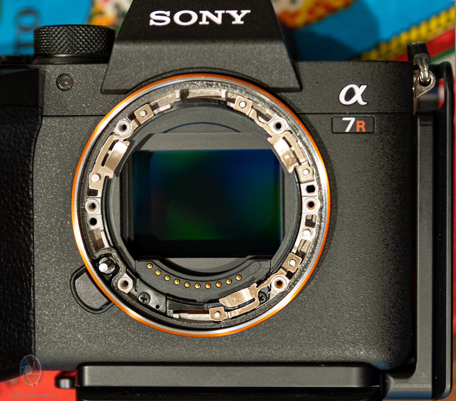
Samuel,
I was able to lift the Sony A7R IV's bayonet right out by removing the 6 screws. Just as easy as with the A7R II.
Here is a quick haldheld picture for you. What do you think?


Sep 13, 2020 at 08:40 PM
inksandpaper
Offline
•
Upload & Sell: Off
p.3 #16 · Sensor and lens tilt and how to DIY adjust your equipment


Fred Miranda wrote:
Samuel,
I was able to lift the Sony A7R IV's bayonet right out by removing the 6 screws. Just as easy as with the A7R II.
Here is a quick haldheld picture for you. What do you think?


Fred!!! What do I think?? I think that's awesome!! Wow, so I don't know what Ilija was saying then about the bayonet not being possible to remove... I had better amend my published posts.

That's so great, so the camera can indeed be shimmed. You would want the McMaster-Carr shims also to be able to support the mount adequately to get into less than 10-micron intervals which the Misumi shims can't go to.


Sep 13, 2020 at 08:57 PM
Fred Miranda
Offline
Admin
Upload & Sell: On
p.3 #17 · Sensor and lens tilt and how to DIY adjust your equipment


inksandpaper wrote:
Fred!!! What do I think?? I think that's awesome!! Wow, so I don't know what Ilija was saying then about the bayonet not being possible to remove... I had better amend my published posts.

That's so great, so the camera can indeed be shimmed. You would want the McMaster-Carr shims also to be able to support the mount adequately to get into less than 10-micron intervals which the Misumi shims can't go to.


Yes, that's what I though. It's exciting since newer Sony full frame bodies have the 6 screw bayonet. (except for the new A7C from a picture I've seen)

Should I get the CIMRS2-3-0.01 or CIMRS2-4-0.01 is fine for 10 micron shims?
I will also order the 0.005 from mcmaster.com.

Hopefully my Kipon Shift + M to EOS adapters will come soon so I can test this out. I think my A7R IV has great parallelism (compared to other bodies I've seen) but it will be interesting to confirm this.


Sep 13, 2020 at 09:09 PM
inksandpaper
Offline
•
Upload & Sell: Off
p.3 #18 · Sensor and lens tilt and how to DIY adjust your equipment


Fred, I think you might just have posted the first ever picture of a 6-screw Sony mirrorless bayonet removed on the web. I've never been able to find such a thing anywhere. Thank you so much for doing this!


Sep 13, 2020 at 09:10 PM
inksandpaper
Offline
•
Upload & Sell: Off
p.3 #19 · Sensor and lens tilt and how to DIY adjust your equipment


Fred Miranda wrote:
Should I get the CIMRS2-3-0.01 or CIMRS2-4-0.01 would be ok for 10 micron?
I will also order the 0.005 from mcmaster.com.

Hopefully my Kipon Shift + M to EOS adapters will come soon so I can test this out. I think my A7R IV has great parallelism (compared to other bodies I've seen) but it will be interesting to see if it's true.


My preference has been to use CIMRS2-3-0.xx for the Sony body rather than CIMRS2-4-0.xx. Joe likes 4mm OD because they are much less fragile. Since you have 4mm OD on hand, try them first? Yes, you'll probably need some 10-micron ones on hand if you intend to shim the camera. Just be careful to avoid the leaf springs if possible.

I think you'll want to order the 0.001" 18-8 stainless steel 'tight-ring shims' from McMaster. 0.005" is too thick and would change your flange distance more than necessary. One or two bags of qty 10 of the 0.001" ones would get you a healthy selection varying from 26-31 microns, from what Joe Holmes told me.

Remember to measure and account for the rotating 'wobble' of your incoming Kipon adapter. It would be very interesting indeed to see how close it is to parallel! Excited


Sep 13, 2020 at 09:19 PM
Fred Miranda
Offline
Admin
Upload & Sell: On
p.3 #20 · Sensor and lens tilt and how to DIY adjust your equipment


inksandpaper wrote:
My preference has been to use CIMRS2-3-0.xx for the Sony body rather than CIMRS2-4-0.xx. Joe likes 4mm OD because they are much less fragile. Since you have 4mm OD on hand, try them first? Yes, you'll probably need some 10-micron ones on hand if you intend to shim the camera. Just be careful to avoid the leaf springs if possible.

I think you'll want to order the 0.001" 18-8 stainless steel 'tight-ring shims' from McMaster. 0.005" is too thick and would change your flange distance more than necessary. One or two bags of qty 10 of the 0.001" ones would get
...Show more →

Wouldn't 0.005 (5 microns) be enough? I mean, it would be already hard to spot a 5-micron skew, why would I need 1 micron (0.001)?

What do you mean by leaf spring?

I will re-read your article to see how to deal with adapter wobble.

Thanks for your insight.
Fred


Sep 14, 2020 at 12:25 AM
1       2              4       5       end


FM Forums | Sony Forum | Join Upload & Sell

1       2              4       5       end


You are not logged in. Login or Register